Stabilogram
The Stabilogram window analyzes postural stability from the relationship between the support base, the distribution of support reactions, and the position of the body’s center of gravity.
Use this window to determine whether the posture represented by the model can be considered stable, how weight is distributed among the supports, and whether there is a slipping risk. The same information can also be displayed directly on the biomechanical model.
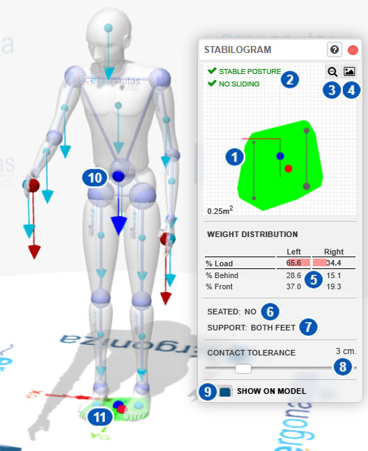
| No. | Area or control | Function |
|---|---|---|
| 1 | Stabilogram | Shows the support base, support positions, reaction distribution, and projection of the center of gravity. |
| 2 | Stability and slipping indicators | Indicate whether the posture is considered stable and whether there is a slipping risk. |
| 3 | Stabilogram zoom | Zooms the stabilogram view in or out. |
| 4 | Stabilogram capture | Captures and downloads an image of the stabilogram. |
| 5 | Weight distribution | Shows how the load is distributed between the left and right supports and between their front and rear areas. |
| 6 | Seated condition | Indicates whether the posture is considered seated and whether this condition was detected automatically or defined by the user. |
| 7 | Detected support type | Identifies the detected support type: one foot, both feet, knees, or hips. |
| 8 | Contact tolerance | Adjusts the tolerance used to determine whether a body segment is in contact with the floor or support. |
| 9 | Show on model | Turns the stabilogram and centers-of-gravity display on the biomechanical model on or off. |
| 10 | Stabilogram on the model | Shows the body’s center of gravity, its projections, and body-segment centers of gravity on the model. |
| 11 | Support base on the floor | Displays the support base associated with the detected supports in the scene. |
Purpose of the window
The stabilogram summarizes the information needed to interpret postural stability. It represents the support base, supports, weight distribution, and the position of the center of gravity projected onto the floor.
A posture is considered stable when the projection of the center of pressure or resultant support force remains within the support base. If the projection falls outside the support base, the posture is interpreted as unstable.
The window also reports possible slipping. This condition depends on the applied horizontal forces, supported loads, and coefficient of friction between the footwear and the floor.
Stabilogram
Area 1 shows the stabilogram.
The green area represents the support base, or footprint. It is the geometric area defined by the detected supports. When the model is supported on both feet, the support base is formed from the foot-floor contact areas and the space between them.
The following graphic elements help interpret the support:
- green lines represent support orientation;
- green circles indicate support points;
- circles associated with the front and rear supports show how reactions are distributed on each foot;
- the diameter of each green circle is proportional to the load carried by that support.
These elements reveal whether weight is distributed evenly or concentrated on a particular support.
Centers of gravity shown
The stabilogram shows two main circles:
- the blue circle represents the projection of the body’s center of gravity onto the floor plane;
- the red circle represents the center of gravity after also accounting for loads supported by the hands and other body segments.
The distance between these points shows the effect of external loads on stability. A load held in the hands or applied to another body segment can shift the resultant and change the interpretation of the posture.
Before interpreting the stabilogram, make sure that the loads defined in the system accurately represent the assessed task.
Review these loads under:
Stability and slipping indicators
Area 2 shows two main indicators:
- whether the posture is considered stable;
- whether there is a slipping risk.
Stability depends on the position of the center of pressure relative to the support base. The posture is considered stable when the center of pressure remains within the footprint and unstable when it lies outside it.
Slipping is assessed from the applied horizontal forces and the available friction between the footwear and the floor. If the horizontal component of the applied loads or forces exceeds the available friction force, the system may indicate a slipping risk.
The available friction force depends, among other factors, on the coefficient of friction defined under Model settings. If the slipping result appears inconsistent, make sure that the entered coefficient accurately represents the surface and footwear used in the assessed task.
Stabilogram zoom
Button 3 enlarges or reduces the stabilogram.
Zooming makes it easier to examine the center of gravity and the supports when points are close together or the support base occupies only a small area of the representation.
Use zoom when you need to determine more precisely whether the center-of-gravity projection lies inside or outside the support base.
Stabilogram capture
Button 4 captures and downloads an image of the stabilogram.
This is useful for documenting the stability result, adding the image to reports, comparing postures, or retaining graphic evidence of the analysis.
Before capturing the image, make sure that the stabilogram scale and displayed information are appropriate.
Weight distribution
Area 5 shows weight distribution among the supports.
The table shows:
- the percentage of the load carried by the left and right supports;
- load distribution toward the front and rear of the supports;
- asymmetry between the two sides of the body.
This information explains how weight is distributed in the analyzed posture. A markedly asymmetric distribution may be consistent with some tasks, but it may also indicate an unbalanced posture or an external load that shifts the center of gravity.
Interpret the table together with the stabilogram and model display.
Seated condition
Area 6 indicates whether the posture is considered seated.
It can show whether the seated condition was:
- detected automatically by the system;
- explicitly defined by the user.
The seated condition changes how supports are interpreted. In a standing posture, the feet are normally the main support. In a seated posture, the feet, knees, thighs, or pelvis may contribute, depending on the detected contact areas. The Backrest option does not add a contact area to the stabilogram or generate a separate reaction.
For more information, see:
Detected support type
Area 7 shows the detected support type.
The system can identify, among other cases:
- one-foot support;
- both-feet support;
- knee support;
- hip support.
This information is important because the support base and reaction distribution depend directly on the detected supports.
If the indicated support type does not match the actual posture, review the model posture, seated condition, and contact tolerance.
Contact tolerance
Control 8 adjusts the contact tolerance.
Contact tolerance defines the margin used by the system to determine whether a body segment is in contact with the floor or support surface. In practical terms, it determines when a foot, knee, hip, or other support is close enough to the contact plane to be treated as an effective support.
A higher value makes contact detection more permissive. A lower value makes it more strict.
The same parameter is also available in the Intelligent menu. The two controls are synchronized: changing contact tolerance in the Stabilogram window also changes it in the Intelligent menu, and vice versa.
If the system does not detect a support that should exist, slightly increase the tolerance. If it detects contacts that should not be treated as actual supports, reduce it.
Show on model
Control 9 turns the stabilogram display on the biomechanical model on or off.
When enabled, the model becomes transparent so the stability elements and centers of gravity remain visible. This relates the information in the window to the body’s actual position in the scene.
Stabilogram display on the model
Area 10 shows the stabilogram representation on the model.
When the display is enabled, it shows:
- the body’s center of gravity;
- the projection of the center of gravity onto the floor;
- the center of gravity including external loads;
- its projection onto the support plane;
- the centers of gravity of the individual body segments;
- reference lines or vectors associated with these centers of gravity.
This representation helps explain why a posture is considered stable or unstable and shows how body segments and external loads contribute to the position of the resultant.
Support base on the floor
Area 11 shows the support base directly on the scene floor.
This display relates the stabilogram footprint to the model’s three-dimensional posture. It is particularly useful for checking whether the support base matches the visible supports and whether the center-of-gravity projection lies within that base.
Effect of external loads
Loads applied to the hands or other body segments can change stability.
A supported load can shift the resultant center of gravity forward, sideways, or in any other direction depending on its magnitude and position. The stabilogram therefore distinguishes between:
- the body’s center of gravity without external loads;
- the resultant center of gravity including supported loads.
If the posture appears stable without loads but unstable when loads are included, review the magnitude, direction, and point of application of the entered forces.
Recommendations for use
Use the following sequence to interpret the stabilogram correctly:
- Visually review the model posture.
- Check which supports have been detected.
- Review the support base shown in the stabilogram.
- Check the position of the center of gravity and the resultant with loads.
- Check whether the posture is considered stable.
- Check whether there is a slipping risk.
- Verify the coefficient of friction in Model Settings.
- Adjust contact tolerance if the detected supports are inconsistent.
- Turn on the model display if you need to examine the spatial position of the centers of gravity and supports.
- Capture the stabilogram if you need to document the analysis.
Related User Manual sections
For a complete interpretation, also see:
Relationship to the Technical foundations
For a more detailed methodological explanation, see these sections of the Technical foundations:
- Support base, center of pressure, and stability
- Support modeling
- Foot-support reaction forces in standing postures
- Stabilogram and support-reaction distribution
- Global slipping
- Partial slipping
- Modeling a seated posture in a chair
- Detecting a seated posture in a chair
- Contacts considered when seated in a chair
- Distribution of support reactions when seated in a chair
These sections explain the calculation of stability, support base, reaction distribution, supports considered in standing and seated postures, and possible slipping.