Joint loads
The Joint loads panel is part of Exertion and displays forces and moments acting at model joints under the analysis conditions.
Values are calculated from posture, applied loads, body-segment weights, and detected supports. The panel provides detailed mechanical loading at each joint as moment and force components.
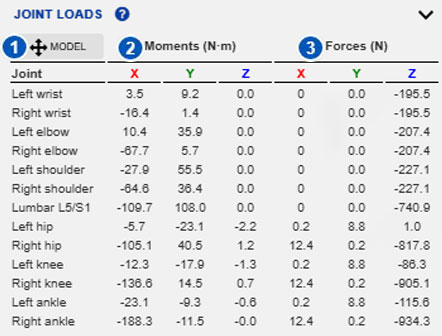
| No. | Area or control | Function |
|---|---|---|
| 1 | Reference system | Switches between the model and global reference systems. |
| 2 | Joint moments | Displays X, Y, and Z moment components in N·m for each joint. |
| 3 | Joint forces | Displays X, Y, and Z force components in N for each joint. |
Purpose of the panel
Joint loads displays estimated internal mechanical loads at the main model joints. Unlike Biomechanical exertion, which focuses on required moment and the capacity or limit used by the active exertion indicator, this panel directly displays force and moment components.
Use it to:
- review joint-load magnitude;
- examine transmission of forces and moments through the body;
- analyze external loads at the hands or other body segments;
- compare mechanical loads between postures;
- interpret the influence of supports, seated posture, or weight distribution;
- complement biomechanical-exertion analysis.
These are biomechanical-model estimates, not direct measurements from a person.
Reference system
Button 1 changes the reference system for forces and moments.
Initially, values use the model reference system, which moves and rotates with the model and facilitates interpretation relative to the body.
Selecting Model can switch to the fixed global reference system. Under the global system, panel values can change when model orientation changes even if the internal posture remains similar.
Thus:
- the model reference system expresses values relative to the human model;
- the global reference system expresses them relative to the fixed scene axes.
Use the model system for body-related joint loading and the global system for scene-related or absolute spatial orientation.
Joint moments
Area 2 displays joint moments in N·m.
Each row is a joint with X, Y, and Z components under the selected reference system.
A joint moment represents the rotational tendency to be balanced at the joint. Its magnitude and sign depend on posture, external loads, body weight, and the selected reference system.
Joint moments are related to biomechanical exertion but are not themselves % maximum recommended exertion (%MRE) or % recommended joint capacity (%RJC). To interpret a moment relative to worker capacity, see:
Joint forces
Area 3 displays joint forces in N, with X, Y, and Z components.
They depend on:
- body-segment weights;
- applied external loads;
- segment positions;
- support distribution;
- ground reaction;
- seated or nonseated condition;
- the reference system used for display.
Before interpreting one value, review the complete posture, entered loads, and detected supports.
Interpreting the Z component
The Z force component requires particular care because it is strongly related to gravity, ground reactions, and support conditions.
When both legs are supported, lower-limb Z reactions generally appear negative, especially without external loads having a positive vertical component. The upward ground reaction must be balanced together with body weight by the forces at the knees, hips, and other lower-limb joints.
When one leg is raised, it no longer receives a ground reaction. Its weight must be supported by muscles and joint forces. Ergoniza Intelligent can therefore assign positive Z forces to joints in the raised leg, interpreted as the effort needed to hold it against gravity rather than a passive reaction to an external force.
Always interpret this with the posture and detected supports.
Relationship with supports
Joint loads are directly conditioned by model supports.
Standing reactions are transmitted mainly through the feet. In seated posture, contacts can include the feet, knees, thighs, or pelvis. The backrest is not modeled as a support with its own reaction.
When enabled, Backrest affects the torso flexion-moment calculation and can change lumbar results, but it does not introduce a new external force on the model.
Interpret joint loads together with:
- detected support type;
- weight distribution;
- center-of-gravity position;
- seated condition;
- posture stability.
See:
Relationship with external loads
Loads at the hands or other body segments can materially change joint loads.
A hand-held load can increase forces and moments at the wrists, elbows, shoulders, trunk, hips, knees, or ankles depending on posture and load position. A load applied directly to a body segment can change nearby joints and support chains.
Verify that loads represent the real task:
An incorrect magnitude, direction, or application point can produce unrepresentative joint forces and moments.
Difference between joint loads and biomechanical exertion
| Panel | What it displays | Primary use |
|---|---|---|
| Joint loads | Mechanical forces and moments at each joint. | Review estimated internal load and its mechanical distribution. |
| Biomechanical exertion | Required moment, active muscle group, population capacity, and capacity or limit used by the active indicator. | Compare required exertion with the corresponding capacity or limit. |
Interpret a high joint moment together with the active capacity or limit:
- %MRE uses a limit that incorporates preventive priority assigned to the body region;
- %RJC uses recommended joint capacity, which in Multiple postures mode can vary with prior exertion and rest;
- % Maximum Isometric Capacity Used uses estimated maximum isometric capacity without changing it according to prior activity.
Absolute moment alone is insufficient.
Effect of changing model orientation
Under the global reference system, values can change when the model’s overall orientation changes because X, Y, and Z are fixed in the scene.
This does not necessarily mean that the model’s actual internal load changed; the same vector may simply be projected onto different global axes.
When comparing postures, keep the reference system consistent and account for any model reorientation.
Interpretation recommendations
- Check the active reference system.
- Review joints with the largest forces or moments.
- Determine whether high values coincide with extreme postures or substantial external loads.
- Review supports and stability in the stabilogram.
- Check whether the posture is seated.
- Review hand and other body loads.
- Use Biomechanical exertion to interpret whether moments are acceptable.
- Use the same reference system when comparing postures.
Use this panel as a mechanical-analysis tool, not a sole risk criterion. Ergonomic assessment should also consider the active exertion or capacity indicator, protected population, duration, repetitiveness, and actual task conditions.
Related manual sections
- Exertion
- Biomechanical exertion
- Exertion and joint-capacity indicators
- Unprotected population
- Support reaction loads
- Stabilogram
- Seated posture
- Load or force at the hands
- Loads on body segments
Relationship with the Technical foundations
For methodological details, see:
- Joint-load calculation
- Joint loads
- Support modeling
- Foot-support reaction forces while standing
- Stabilogram and support-reaction distribution
- Modeling seated posture on a chair
- Distribution of support reactions while seated on a chair
- Limitations in calculating biomechanical moments and exertion
These sections explain joint-force and moment calculations, support influence, ground-reaction interpretation, and methodological limitations.